High-Temperature Air-Cooled Bipolar Plates for Aerospace Fuel Cells
Simulation of a key component inside an aircraft fuel cell, checking that fuel and air spread evenly and heat escapes as the stack heats and cools, backed up with 3D printed prototypes.
Identified 150 °C as the best operating point, with even pressure held from 100 to 200 °C
Individual project. Design, CFD, cross checking and prototyping my own.
- 150 °C
- identified best operating point
- 100–200 °C
- range with even pressure held
- 96
- channels at 0.9 mm width
- 2 solvers
- AVL FIRE M cross checked in COMSOL
Overview
A fuel cell turns hydrogen into electricity. Inside it, thin plates do three jobs at once: spread hydrogen and air evenly, carry the current out, and take the heat away. How well they are designed decides how much power the cell makes and how long it lasts.
Putting one on an aircraft makes that harder. The stack heats and cools repeatedly, weight matters more than on the ground, and liquid cooling adds both mass and a leak path. Air cooling avoids the liquid loop but makes the plate work far harder.
What I did
- Designed the plate and its 96 channel flow field in CAD, sized around the active area and the pressure drop that channel width allows.
- Built the CFD model in AVL FIRE M and ran it from 90 to 200 °C, spanning the window a high temperature PEM cell actually operates in.
- Cross checked the key results in COMSOL so no conclusion rested on a single solver.
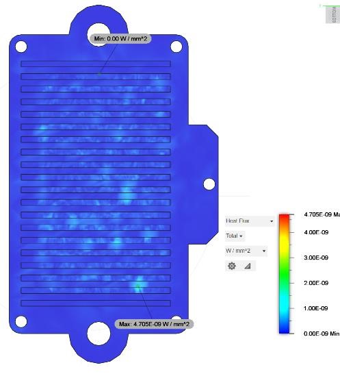
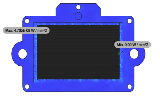
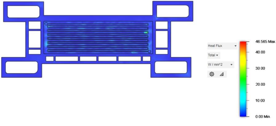
- Used Fusion 360 thermal and structural analysis to find where the plate is most loaded as it expands and contracts through the cycle.
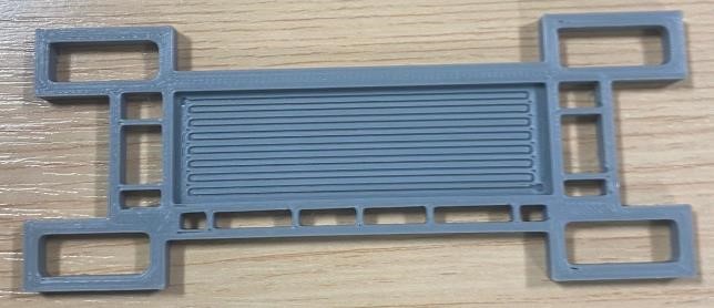
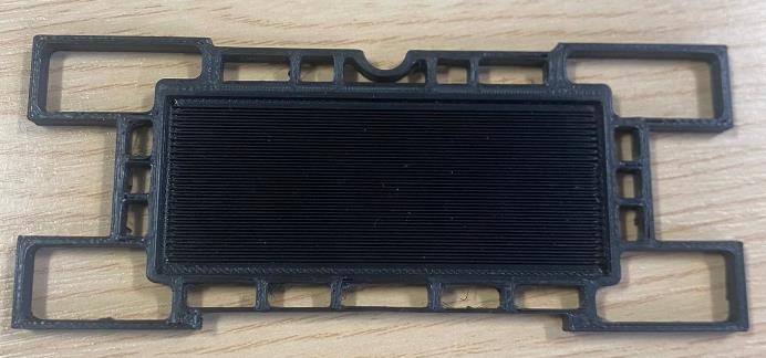
- 3D printed prototypes to prove the 0.9 mm channels were manufacturable and the sealing faces met before committing to tooling.
Methods
- CFD in AVL FIRE M across 90 to 200 °C, cross checked in COMSOL
- Thermal and structural analysis in Fusion 360 through the temperature cycle
- 96 channel flow field at 0.9 mm width, designed in CAD and 3D printed
- Velocity, pressure, mass flow, current density and condensation analysis
- Materials and coatings review against DOE bipolar plate targets
Key results
- 01
150 °C is the operating point to design around. Mass flow rate peaks there, and above it the cooling system must run continuously to keep thermal stress from damaging the plate.
- 02
No part of the cell gets starved of reactant. Pressure stayed even across the plate over the whole 100 to 200 °C sweep, and velocity shifted only around 0.001 m/s between 110 and 120 °C.
- 03
The plate stays inside its structural limit. Thermal loading came out at 1.705E-9 W/mm² at the design condition and 1.565E-9 W/mm² at 200 °C, so the top of the aerospace envelope is covered.
- 04
Flooding stops being a concern above 150 °C. Condensation only forms below that, which removes the limitation that normally constrains low temperature PEM cells.
Outcome
The project produced a workable plate design and, more usefully, a temperature map of how it behaves, which is what an aircraft duty cycle demands. It names the operating point, shows reactant distribution holding across the range, confirms the structural limit is respected, and shows air cooling takes weight and a leak path out of the aircraft.